THE DISTANCE MECHANICS OF SURF SPEY CASTING:Long-Range Casts on Regional BeachesBy Mark Severino
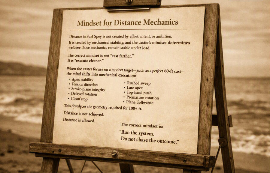
Mindset for Distance MechanicsDistance in Surf Spey is not created by effort, intent, or ambition. It is created by mechanical stability, and the caster’s mindset determines whether those mechanics remain stable under load.The correct mindset is not “cast farther.” It is “execute cleaner.”When the caster focuses on a modest target - such as a perfect 60 ft cast - the mind shifts into mechanical execution:
• apex stability
• tension direction
• stroke plane integrity
• delayed rotation
• clean stopThis mental state produces the geometry required for 100+ ft. The caster did not try for 100. The caster created the conditions that produce 100.When the caster focuses on a large target - such as “throw 100 ft”- the mind shifts into outcome chasing:
• rushed sweep
• late apex
• top hand push
• premature rotation
• tension collapse
• plane deviationThis mental state destroys the geometry required for distance. The cast hits a wall not because 100 ft is unreachable, but because the mindset collapsed the mechanics that make 100 ft possible.Distance is not achieved. Distance is allowed.The correct mindset is:
“Run the system. Do not chase the outcome.”When the caster maintains this mindset, distance emerges as a byproduct of geometry, not effort.
PURPOSE OF THIS ARTICLEThis article defines the mechanical architecture required to increase the Spey casting distance in predictable, measurable increments.It establishes the doctrine governing:
• Anchor geometry
• D-loop mass and height
• Rod load timing
• Stroke length
• Line speed generation
• Running line efficiencyThis is not a “tips” article. This is the mechanical law behind distance.THE FIRST PRINCIPLE OF DISTANCEThe rod only loads when the line remains under continuous tension.Every distance failure- anchor collapse, D-loop drop, tailing loop, loss of shoot- comes from a break in tension.Every increase in distance comes from reducing tension loss.Distance is not power. Distance is efficiency.III. THE DISTANCE LADDERDistance increases occur in three discrete mechanical jumps:
1. 60 → 80 ft
2. 80 → 100 ft
3. 100 → 120 ftEach jump requires a different mechanical upgrade. You cannot skip a rung.IV. 60 → 80 FT: GEOMETRY AND STABILITYObjective:
Establish a stable anchor and a structurally correct D-loop.
Mechanical Requirements1. Forward, Light Anchor
The anchor must land forward of the casting shoulder with minimal stick. A heavy anchor kills distance before the cast begins.2. Extended Casting Arc
Move from a compact stroke to a slightly longer one. This allows the rod to load deeper without overpowering.3. Smooth Acceleration
Acceleration must be continuous and unbroken. Early rotation destroys tension and collapses the D-loop.4. D-Loop Stability
The D-loop must form:
• High
• Deep
• Directly opposite the target
• Under continuous tensionA stable D-loop is the engine of the cast.What This Unlocks
A clean 80 ft cast is the product of geometry, not strength.V. 80 → 100 FT: LINE SPEED AND SHOOT EFFICIENCYObjective:
Increase line speed while maintaining anchor and D-loop integrity.Mechanical Requirements1. Late Rotation
Rotation must occur in the final portion of the stroke. This produces maximum rod load and maximum tip speed.2. Sharper Stop
The stop is the single largest determinant of loop speed. A crisp stop produces a tight, high apex loop.3. Running Line Control
Running line must be:
• Clean
• Stretched
• Held in large, even coils or a stripping basket
Any drag kills distance.4. Straight Line Rod Tip Path
The rod tip must travel in a straight line during the power stroke. Deviation produces tailing loops and energy loss.What This Unlocks
100 ft requires:
• High line speed
• Efficient shoot
• Clean anchor
• Deep D-loopThis is the plateau where most casters stop. The next jump requires precision, not power.VI. 100 → 120 FT:
EFFICIENCY, PRECISION, AND ZERO DRAGObjective:
Eliminate all sources of drag and maximize stored energy.
Mechanical Requirements1. Perfect Anchor Placement
The anchor must be:
• Forward
• Light
• Minimal
• Aligned 180° opposite the target
Any excess anchor kills the cast.2. Maximum D-Loop Mass and HeightA competition-grade D loop is:
• Deep
• High
• Fully tensioned
• Heavy with line massThis is the primary energy reservoir for 120 ft.3. Long Stroke with Controlled Drift
Drift increases stroke length without adding force. It sets the rod in the optimal position for late rotation.4. Zero Running Line Drag
The running line must leave the hand without friction. This requires:
• Clean coils
• No water tension
• No tangles
• No premature release5. Timed Release
The running line must be released at the exact moment the forward cast loop stabilizes. Early release collapses the loop. Late release kills the shoot.What This Unlocks
120 ft is not a power cast. It is a precision cast.VII. THE DISTANCE MECHANICS TABLE60 → 80 ft Anchor + D-loop stability Geometry creates a load
80 → 100 ft Line speed + late rotation Speed creates shoot
100 → 120 ft Precision + efficiency Efficiency preserves energyVIII. THE LAW OF DIMINISHING TENSION LOSSAs distance increases, the tolerance for error decreases.• At 60 ft, you can make multiple mistakes and still succeed.• At 80 ft, you can make one mistake and still succeed.• At 100 ft, you can make half a mistake and still succeed.• At 120 ft, you cannot make a single mistake.Distance is the measurement of how little tension you waste.THE FINAL PRINCIPLEDistance is not added. Distance is revealed.When anchor, D-loop, stroke, and shoot are aligned, the cast becomes efficient enough to expose the distance that was always available.APPLICATION TO SURF SPEYSurf Spey magnifies every distance mechanic because:
• Water tension is higher
• Wind is constant
• Line stick is amplified
• Timing windows are shorterThe mechanics in this article are not theoretical. They are field-tested in the Gulf.
Tracking the Chest Shoulder Seam for Maximum Spey DistanceLong-range Spey casting depends on one forward stroke truth: the rod tip must travel down the chest shoulder seam - the inner anatomical seam where the pectoral mass transitions into the anterior deltoid.When the rod tip stays on this plane, the forward stroke remains straight, tensioned, and capable of producing a tall apex and long unroll. When it drifts toward the center of the chest, distance geometry collapses.This page explains why seam alignment is mandatory for distance, and how center chest positioning destroys the forward stroke mechanics required for long casts.1. The Seam as the Distance Plane
For distance, the forward stroke must produce:
• a straight rod tip path
• a vertical apex
• a tensioned forward leg
• a long acceleration lane
• a stable anchorThe chest shoulder seam is the only anatomical plane that satisfies all five requirements. It keeps the rod tip outside the anchor, aligns both hands in a single casting plane, and allows the rod to express full bottom hand acceleration without curvature.Any deviation from this seam reduces distance potential immediately.2. How Center Chest Positioning Breaks Distance GeometryCenter chest alignment is the most common distance-limiting error. It seems small, but it breaks the forward stroke at every structural point.A. Inward Rod Tip Curve
Center chest forces the rod tip inside the casting plane. This creates an inward curve, producing:
• wide loops
• low line speed
• reduced unroll distance
A curved rod tip path cannot produce a long cast.B. Diagonal Forward Lane
The seam produces a vertical forward lane. Center chest produces a diagonal inward lane.
Diagonal lanes cause:
• apex collapse
• early unroll
• sagging belly
• reduced carryDistance requires a tall apex; center chest destroys it.C. Loss of Anchor Pressure
Distance depends on a stable, tensioned anchor. Center chest pulls the rod tip inside the anchor, reducing pressure and causing slip.
Anchor slip = no load = no distance.D. Shortened Forward Stroke
Center chest shortens the forward lane because:
• the rod tip starts too far inside
• the stroke becomes diagonal
• the rod reaches the stop prematurelyShort stroke = low acceleration = low distance.3. Why Seam Tracking Increases DistanceWhen the rod tip tracks the chest shoulder seam:
• the rod tip stays outside the anchor
• the forward lane stays vertical
• the apex rises
• the forward leg stays tensioned
• the stroke length increases
• bottom hand acceleration expresses fully
• the loop tightens and carries fartherThis is the geometry required for 100 foot+ Spey casts.4. Distance DoctrineFor long range Spey casting:
The forward stroke must track the chest shoulder seam. Center chest is a collapse plane.Distance is not created by power. Distance is created by geometry, and the seam is the forward stroke geometry that makes long casts possible.
THE EXTENDED LEVERAGE FORWARD STROKEMaximizing Distance and Line Speed in the Gulf Surf1. Purpose
The forward stroke in the surf is not the same forward stroke taught in river Spey.The Gulf demands a longer lever, a higher apex, and a more linear acceleration path to overcome:
• coastal headwinds
• lateral drift
• collapsing wave energy
• trough to bar reach requirementsTraditional instruction, “keep the hands close to the chest,” is mechanically insufficient in this environment.The surf requires an extended-leverage stroke: a forward-reaching top hand and a bottom-hand pull to the solar plexus that produces maximum linear velocity with minimal effort.This stroke is the mechanical evolution Surf Spey requires.2. The Casting Chain: Sweep → Drift → Slide → Forward StrokeThe forward stroke is not a standalone event. It is the fourth link in a positional chain:1. Sweep establishes direction and anchor lane.2. Drift raises the rod tip to the High Apex.3. Slide sets the forward stroke plane and removes micro slack.4. Forward Stroke accelerates the system in a straight line and finishes with late rotation.If any link is contaminated, the forward stroke becomes compensatory.3. The High Apex: The Launch PlatformThe forward stroke begins on the same plane established by Drift and Slide. The High Apex must be:
• high
• rearward
• level
• tension neutralThis geometry is non-negotiable. A low apex collapses the stroke. A drifting apex forces the caster into early rotation. A tilted apex opens the loop and kills distance.The High Apex is the launch platform for the forward stroke.4. Top Hand: Forward Extension (The Elbow-Based V)The top hand does not simply “reach forward.” It opens the elbow into a long, shallow V-shaped angle, extending the lever arm without flaring the arm or breaking vertical plane discipline.This “V” is an elbow geometry.
The Elbow-Based V Provides Four Mechanical Advantages1. Lever Lengthening: Opening the elbow forward increases the effective lever arm, allowing the rod tip to travel farther in a straight line before rotation begins.2. Apex Preservation The extended elbow stabilizes the rod tip on the high, level plane established by Drift and Slide, preventing tip dip or lift during acceleration.3. Wind Vector Stability The elongated V resists crosswind torque, keeping the rod tip tracking vertically even in heavy Gulf headwinds.4. Delayed Rotation: The elbow forward geometry naturally delays rotation until the final inches of the stroke, producing the tight, compressed, wind-cutting loops required in the surf.This is a mechanical V, created by the elbow opening forward, thereby extending the lever while maintaining strict linear geometry.5. Bottom Hand: The Solar Plexus PullThe bottom hand pulls directly toward the solar plexus, not the stomach. This finish point is critical.Why the Solar Plexus Matters
• keeps rotation late
• compresses the loop
• prevents over-rotation
• maintains a vertical tip path
• stabilizes the rod tip in wind
• preserves the high apex through the stopA stomach-level finish collapses the apex, opens the loop, and kills distance. The solar plexus finish is the mechanical anchor of the stroke.6. Linear Geometry: The Heart of the Forward StrokeThe forward stroke in the surf is a linear pull that ends in rotation, not a rotational stroke that happens to be linear.Correct Forward Stroke Geometry
• rod tip travels in a straight, level line
• acceleration is smooth and progressive
• rotation occurs only at the end
• stop is crisp and highIncorrect Geometry
• arcing tip path
• early rotation
• dipping or lifting
• long, soft stopLinear geometry produces the tight, fast loops required to punch through Gulf headwinds.7. Integration With Surf Spey DoctrineThe extended leverage stroke integrates directly with the three pillars of the Surf Spey Casting Perspective:A. Linear Geometry
The elongated “V” and solar plexus pull create the longest possible straight-line acceleration path.B. Reset Tension
The Slide sets the tension; the forward stroke preserves it. Any slack introduced here collapses the apex and destroys the stroke.C. Anchor Lane Management
A clean anchor lane allows the forward stroke to remain purely linear. A drifting anchor forces the caster into compensatory angles that kill distance.When these doctrines align, the forward stroke becomes inevitable.8. Equipment SynergyHeavy Skagit heads amplify the stroke’s mechanical advantages:
• deeper load
• longer lever
• higher apex stability
• increased line mass for wind penetration
• more efficient energy transferThe equipment does not create distance; it reveals the caster’s mechanics.9. The Result: Velocity, Stability, PenetrationWhen the extended leverage stroke is executed correctly:
• the rod loads deeply
• the tip tracks level
• rotation occurs late
• the loop forms tight and fast
• the line accelerates linearly
• the cast slices through wind and wave energyThis is the stroke that makes Surf Spey viable in the Gulf.Summary
The extended leverage forward stroke is the mechanical evolution required for surf conditions.Top hand forward. Bottom hand to the solar plexus. Elbow-based V Linear pull. Late rotation. High apex preserved.This is how you generate the velocity, stability, and loop integrity needed to reach the trough, cut through headwinds, and deliver flies with authority in the Gulf surf.
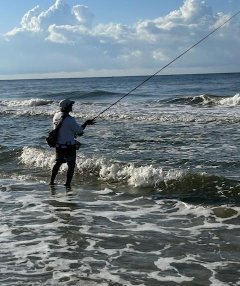
ROTATION & TRAJECTORYThe Final Mechanical Events of the Surf Spey Forward Stroke1. Purpose
Rotation and Trajectory are the final mechanical expressions of the forward stroke. Translation builds the platform. Rotation releases stored energy. Trajectory determines how that energy travels through space.In surf conditions, these two events must be unified. Rotation without Trajectory wastes energy.Trajectory without correct Rotation produces unstable geometry.Rotation is the moment of unloading. Trajectory is the direction of that energy. Together, they define the Surf Spey flight path.2. Rotation: The Moment of UnloadingRotation is the instant at which the rod transitions from linear translation to angular displacement.It is the only moment where line speed is created.
Rotation must be:
• late
• crisp
• vertical
• apex preserving
• plane consistent
Early rotation collapses Surf Spey, mechanics. Late rotation amplifies them.2.1 What Rotation IsRotation is the angular unloading of the rod that:
• tightens the loop
• compresses the line
• drives the tip into the stop
• releases stored energy cleanlyRotation is not a wrist flick. It is a whole-rod angular event initiated by the bottom-hand pull and finished by the top-hand stop.2.2 When Rotation OccursRotation happens only after:
• Sweep sets direction
• Drift establishes the High Apex
• Slide removes slack
• Translation accelerates linearly2.3 Why Rotation Must Be LateLate rotation:
• preserves the apex
• maintains a straight tip path
• compresses the loop
• maximizes line speed
• stabilizes the cast in headwindEarly rotation:
• dips the tip
• opens the loop
• kills distance
• destabilizes the cast in the wind
Late rotation is nonnegotiable.2.4 The Solar Plexus FinishRotation completes when the bottom hand reaches the solar plexus, not the stomach.Solar plexus finish:
• keeps rotation late
• maintains vertical plane
• compresses the loop
• prevents over-rotation
• preserves apex through the stop
This finish point anchors the correct rotation.3. Trajectory: The Direction of EnergyTrajectory is the launch angle created at the moment of the stop. It determines:
• apex height
• loop stability
• wind penetration
• distance ceilingIn the surf, the trajectory must be:
• high
• level
• wind cuttingTrajectory is not “aiming high.” Trajectory is the extension of the High Apex.3.1 What Trajectory IsTrajectory is the continuation of the apex plane into space. It is set before the line leaves the rod tip at the instant of the stop.3.2 The Apex Determines Trajectory
The apex must be:
• high
• levelCorrect apex = correct trajectory. Incorrect apex = incorrect trajectory.3.3 Wind and TrajectoryIn Gulf headwinds:
• low trajectory collapses
• drifting trajectory opens the loop
• tilted trajectory destabilizes the tip
High, level trajectory cuts wind cleanly.3.4 Trajectory and DistanceDistance is not created by force. Distance is created by:
• correct apex
• correct translation
• late rotation
• high trajectoryTrajectory determines how long the loop remains stable before gravity and wind collapse it.4. Integration: Rotation - TrajectoryRotation and Trajectory are consequences of the forward stroke.Rotation ends at the stop. The trajectory begins at the stop.Correct Coordination:
• linear translation
• late rotation
• crisp stop
• high, level trajectory
• tight, fast loop
• wind penetration
• distanceIncorrect Coordination:
• early rotation
• tip dip
• low apex
• open loop
• wind collapse
• lost distanceThe forward stroke sets the geometry. Rotation releases it. Trajectory carries it.5. Doctrine AlignmentA. Linear Geometry
Rotation must occur at the end of a straight line tip path. The trajectory must continue that straight line into space.B. Reset Tension
Slide resets tension. Rotation preserves it. Trajectory expresses it.C. Anchor Lane Management
A clean anchor lane keeps rotation vertical. Vertical rotation produces a high, level trajectory.Anchor → Apex → Rotation → Trajectory. This is the Surf Spey chain.6. Equipment InteractionCorrect load amplifies Rotation and Trajectory:
• deeper load
• higher apex stability
• stronger wind penetration
• cleaner loop formation
• more efficient energy transferLoad depth determines how much rotational energy the rod can store before unloading.The rod does not create a trajectory. The caster does. The rod reveals it.7. Rotation & Trajectory Failure ModesRotation Failures
• Early rotation - tip dip, open loop
• Wrist-driven rotation - diagonal plane, unstable apex
• Over rotation, forward tilted apex, collapsing trajectory
• Under rotation - incomplete unload, weak loopTrajectory Failures
• Apex too low - forced high aim, unstable loop
• Apex too far forward - collapsing loop, wind failure
• Tilted apex - diagonal loop plane
• Compensatory trajectory - caster “aims high” instead of building correct geometry8. Result: The Surf Spey Flight PathWhen Rotation and Trajectory are executed correctly:
• the rod unloads cleanly
• the tip tracks level
• the loop forms tightly and fast
• the line accelerates linearly
• the apex remains high
• the trajectory stays stable
• the cast penetrates the wind
• the fly reaches the trough with authority
This is the Surf Spey flight path.Summary
Rotation is the moment of unloading. Trajectory is the direction of that energy. Together they form the final mechanical expression of the forward stroke.This is how Surf Spey delivers distance, stability, and penetration in the Gulf.
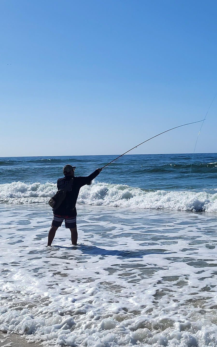
FOLLOW THROUGHThe Final Event After Rotation and Trajectory1. Purpose
Follow-through is the controlled lowering of the rod after the cast is complete. It does not create distance, shape the loop, or influence trajectory. Its only job is to let the fly and line land cleanly and tension neutral in the surf.2. What Follow Through IsFollow-through is a vertical, delayed descent of the rod tip once:
• rotation is finished
• the stop is held
• the loop has cleared the rod tip
• trajectory is already set
It is not a chase, push, or guide. It is simply the rod settling after delivery.3. TimingCorrect timing:
Hold the stop → let the loop clear → lower the rod.Early lowering collapses the apex and opens the loop. Late lowering stiffens the landing and adds slack.4. MechanicsCorrect follow-through:
• vertical tip descent
• smooth and tension neutral
• no forward reach
• no diagonal drop
• no rotationIt positions the rod for immediate strip set readiness, which is the surf equivalent of “connection.”Summary
Follow-through finishes the cast without altering it.Stop. Wait. Lower. Strip.
This is the Surf Spey follow-through.
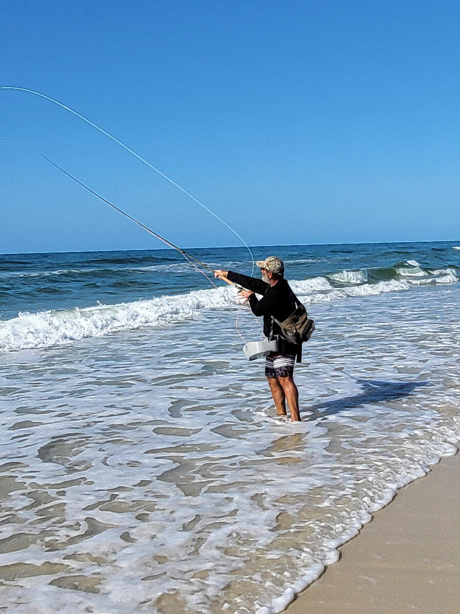
EXTENDED TOP HAND MECHANICSPurpose of This Article
This article defines the mechanical architecture behind the extended top hand and explains how stroke length, plane integrity, and late rotation combine to increase Surf Spey distance in predictable, measurable increments. This is not a “tip.” This is mechanical law.I. THE FIRST PRINCIPLE OF THE EXTENDED TOP HAND
The rod only loads when the line remains under continuous tension. The extended top hand increases stroke length, which increases the duration of tension, which increases stored energy.Distance is not power. Distance is efficiency. Stroke length is efficiency.II. MECHANICAL CHAIN
Extended Top Hand → Longer Linear Stroke → Apex Preservation → Late Rotation → Line Speed → Distance1. Forward, Linear Extension
The top hand extends forward on the casting plane, opening the elbow into a shallow V. This increases the effective lever arm and lengthens the linear stroke before rotation begins.2. High, Level Apex
The extended top hand stabilizes the rod tip on the high apex established by Drift and Slide. This prevents tip dip, tip lift, and plane collapse.3. Straight Line Rod Tip Path
The extended lever keeps the rod tip traveling in a straight line, which is mandatory for:
• loop height
• loop stability
• tension preservation
• long unroll4. Delayed Rotation
The elbow forward geometry naturally delays rotation until the final inches of the stroke. Late rotation produces maximum rod load and maximum tip speed.5. Solar Plexus Finish
The bottom hand finishes at the solar plexus, not the stomach. This preserves apex height, compresses the loop, and prevents over-rotation.III. WHAT THIS UNLOCKS
The extended top hand unlocks:
• longer acceleration lane
• higher apex stability
• tighter, faster loops
• increased line speed
• deeper rod load
• more efficient shoot
This is the geometry required for 100+ ft casts in the surf.IV. FAILURE MODES
1. Upward Reach Instead of Forward Reach
Creates tip lift, opens the loop, kills tension.
2. Rotational Setup
Shortens the stroke and collapses the apex.
3. Low Apex
Destroys trajectory and forces compensatory “aiming high.”
4. Early Rotation
Eliminates stroke length and produces wide, collapsing loops.V. DISTANCE DOCTRINE
The extended top hand lengthens the linear stroke and preserves the high apex. Together, they create sustained acceleration and reveal the distance already present in the system.VI. INTEGRATION WITH THE DISTANCE LADDER
60 → 80 ft
Extended top hand increases stroke length and stabilizes geometry.
80 → 100 ft
Extended top hand preserves apex height and enables late rotation.
100 → 120 ft
Extended top hand maximizes linear acceleration and eliminates tension loss.VII. APPLICATION TO SURF SPEY
Surf conditions magnify the importance of the extended top hand because:
• wind shear destabilizes the apex
• wave pulse collapses geometry
• lateral drift shortens stroke length
• water tension increases anchor sensitivityThe extended top hand is not optional in the surf. It is mandatory.VIII. SUMMARY
Extended top hand. High apex. Linear stroke. Late rotation. Solar plexus finish. Tension preserved. Distance revealed.
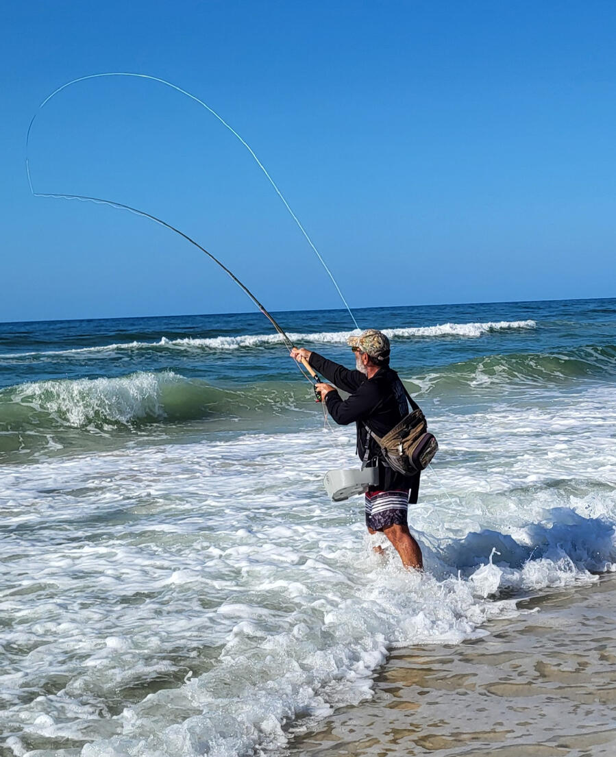
THE HIGH APEX MECHANICSThe Launch Platform of Surf Spey DistancePurpose of This Article
This article defines the mechanical architecture of the High Apex - the geometric platform that determines stroke length, rotation timing, trajectory height, loop stability, and distance ceiling in Surf Spey casting.The High Apex is not a “tip.” It is the central structural requirement for long-range casts in the surf.I. THE FIRST PRINCIPLE OF THE HIGH APEXThe forward stroke only succeeds when the rod tip begins on a high, level, rearward apex. Every distance failure - low trajectory, early rotation, collapsing loop, sagging belly, anchor slip - originates from an apex error.Distance is not power. Distance is apex geometry.II. THE APEX CLOCKVertical Rod Tip Clock for Apex GeometryThis clock defines rod tip position during Drift, Slide, and Apex formation.12 o’clock - straight up • pure vertical • too high for Surf Spey • produces tip lift and premature rotation1 o’clock — high, slightly rearward • acceptable for moderate distance • limited stroke length2 o’clock — high, rearward, level • perfect apex position • maximum stroke length • maximum apex stability • maximum late rotation potential • maximum trajectory height • maximum distance ceiling2 o’clock is the correct Surf Spey apex position.III. WHERE THE TURN TAKES PLACEThe Rotational Return on the Casting PlaneThe Turn is a controlled rotational return on the casting plane. It rotates the rod tip forward from the rearward sweep position and sets the geometry for Drift, Slide, and the High Apex.Correct Turn sequence:
1. Sweep rotates the rod tip back (rearward on the casting plane)
2. Turn rotates the rod tip forward (still on the same plane, no diagonal drift)
3. Drift lifts the rod tip vertically (to the apex clock)
4. Rod tip arrives at 2 o’clock (High Apex established)The Turn is a rotation, but it is a positional rotation, not a power rotation. It does not create line speed. It sets geometry.IV. TERMINAL SWEEP POINTThe Rearward End of the Sweep on the Casting PlaneThe Terminal Sweep Point is defined by:1. Rearward Casting Plane Position
The sweep finishes behind the caster on the rearward section of the casting plane, behind the chest shoulder seam.2. Directional Completion on the Plane
The rod tip has completed its directional travel along the anchor lane and reached the rearward end of that plane.3. Plane Consistent Position
The rod tip remains on the same vertical casting plane the forward stroke will later use. No diagonal drift. No forward lift. No off plane movement.The Turn rotates forward from this point. The apex is built directly above it.V. WHAT THE HIGH APEX ISThe High Apex is the rod tip position established after Drift and Slide:
• high • rearward • level • tension neutral • directly above the rearward sweep plane position • positioned at 2 o’clock on the apex clockThis is the launch platform for the forward stroke.VI. MECHANICAL CHAINHigh Apex → Straight Stroke Plane → Delayed Rotation → High Trajectory → Long Unroll → Distance1. Apex Height
Produces tall loop apex, long acceleration lane, and stable anchor.2. Apex Rearward Position
Lengthens the stroke, increases tension duration, and delays rotation.3. Apex Level
Prevents tip dip, tip lift, and diagonal loop plane.4. Apex Tension Neutrality
No slack. No premature load. No drift contamination.Slack at the apex destroys the stroke before it begins.VII. WHAT THE HIGH APEX UNLOCKSThe High Apex unlocks:
• maximum stroke length • maximum tension preservation • maximum late rotation stability • maximum trajectory height • maximum wind penetration • maximum unroll distanceThe apex is the single largest determinant of distance ceiling.VIII. FAILURE MODES1. Low Apex
Collapsing loop, early unroll, sagging belly, reduced carry.2. Forward Apex
Early rotation, short stroke, low line speed, unstable trajectory.3. Tilted Apex
Diagonal loop plane, wind instability, apex collapse.4. Drifting Apex
Slack introduction, premature load, compensatory stroke, tension collapse.IX. DISTANCE DOCTRINEThe apex must sit high, level, and rearward at the 2 o’clock position, directly above the rearward end of the casting plane. Rearward apex geometry lengthens the stroke, delays rotation, preserves tension, and creates the launch platform required for long- ange Surf Spey casts.X. INTEGRATION WITH THE DISTANCE LADDER60 → 80 ft
High apex stabilizes the D loop and anchor.80 → 100 ft
High apex enables late rotation and high line speed.100 → 120 ft
High apex determines trajectory height and loop stability.XI. APPLICATION TO SURF SPEYSurf conditions magnify apex mechanics:
• wind shear destabilizes low apex • wave pulse collapses forward apex • lateral drift tilts apex • water tension punishes slack at apexThe High Apex is mandatory in the surf.XII. SUMMARYHigh apex. 2 o’clock. Rearward. Level. Plane consistent. Tension neutral. Turn rotation correct. Stroke plane aligned. Late rotation preserved. High trajectory stabilized. Long unroll achieved. Distance revealed.

ENERGY TRANSFER MECHANICS1. Energy Transfer Mechanics define how kinetic energy is created, preserved, and delivered through the Surf Spey stroke sequence. It establishes the continuity rules that prevent energy loss between phases and ensures that the forward stroke receives a stable, directional load capable of producing maximum distance under surf conditions.Energy transfer is not a “moment” in the cast - it is a chain of mechanical events. Any break in the chain reduces distance.2. The Energy Chain (Five Link Model)Energy moves through the cast in five discrete links:Link 1 - Sweep Load
The Sweep creates the initial load vector.
• Load direction: rearward, level, plane aligned
• Load type: angular momentum + rod deflection
• Requirement: plane integrity; no vertical collapse. If the Sweep collapses, the entire chain collapses.Link 2 - Turn Continuity
The Turn preserves Sweep energy by rotating the rod on the same plane.
• No energy creation here - only preservation
• Rotation must be smooth, without tip stall
• The Turn sets the rod up for Drift without tension spikes. If the Turn introduces slack, the chain loses continuity.Link 3 - Drift Stabilization
Drift vertically relocates the rod tip to the apex without adding or removing energy.
• Apex position: 2 o’clock
• Drift must be tension neutral
• Rod tip must remain stable; no wobble. Drift is a stabilizer, not a power move.Link 4 - Slide Alignment
Slide removes micro slack and aligns the rod on the forward casting plane.
• Slide is the only link that “prepares” energy for release
• It does not add power; it ensures the rod is ready to accept power
• Slide must be minimal and controlled. If Slide is skipped, the forward stroke begins with slack - distance dies.Link 5 - Forward Stroke Release
The Forward Stroke converts stored load into forward trajectory.
• Stroke path: straight, level, chest shoulder seam plane
• Release: controlled acceleration to a crisp stop
• Stop orientation: ≈ 11 o’clock. This is the only link where energy is expressed.3. Continuity Rules
Energy transfer obeys three non-negotiable rules:Rule 1 — No Slack Between Links
Slack destroys continuity. Every link must hand off energy cleanly to the next.Rule 2 — Plane Integrity Must Be Preserved
Energy cannot transfer across collapsing planes. Rearward plane → apex → forward plane must remain geometrically stable.Rule 3 - Apex Must Be a Position, Not a Direction
Energy does not “travel along the clock.” The apex is a rod tip location, not a path.4. Energy Loss Mechanisms
Distance failures come from predictable energy leaks:
• Plane collapse (vertical dip during Sweep or Turn)
• Slack introduction (Turn or Slide errors)
• Apex wobble (unstable Drift)
• Premature rotation (forward stroke begins too early)
• Soft stop (energy dissipates instead of launching)Each leak reduces the forward stroke load and shortens distance.5. Energy Transfer in Surf Conditions
Surf introduces external resistance that affects the chain:
• Hydrodynamic drag increases Sweep load requirements
• Wind shear demands higher apex stability
• Lateral current requires stronger plane integrity
• Wave timing affects when the forward stroke can be releasedDistance mechanics must adapt to these modifiers without breaking continuity.6. Summary
The Energy Transfer Doctrine defines the mechanical continuity that makes Surf Spey distance possible. If the chain is intact:
• Load is created
• Load is preserved
• Load is stabilized
• Load is aligned
• Load is releasedIf any link fails, the distance fails.